Haisi Measurement and Control Technology


IMU300 High-Precision 6-Axis MEMS IMU | ±500°/s, ±10g, RS422 Interface

PRODUCT PARAMETERS
Description
Inertial Measurement Unit
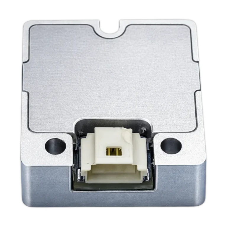
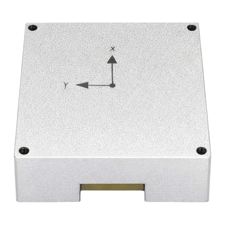
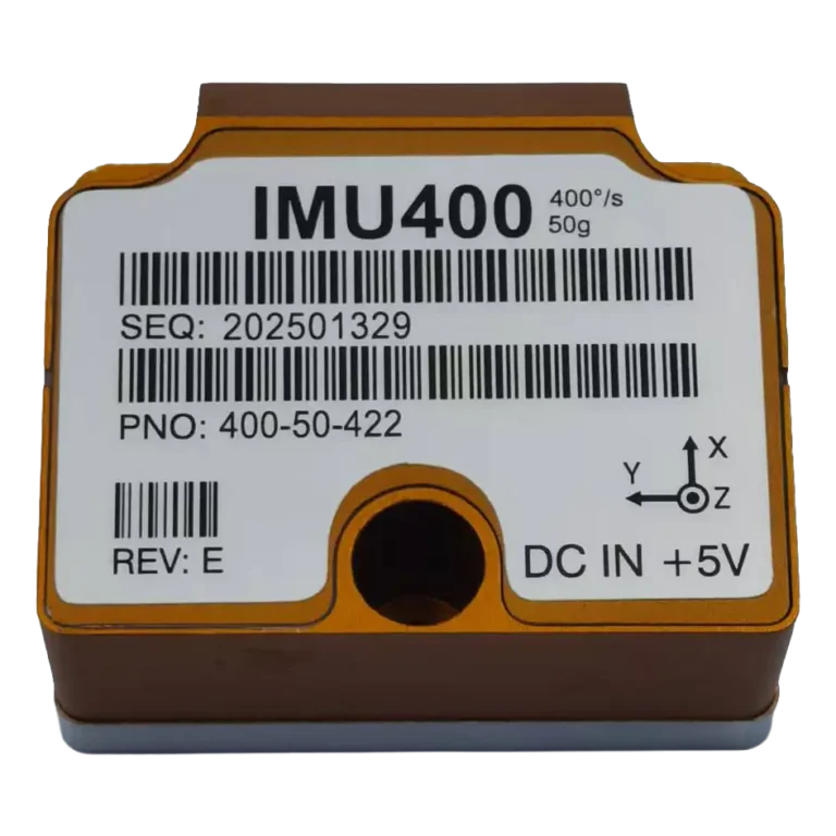
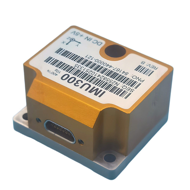
The IMU300 is a high-performance, 6-axis Inertial Measurement Unit (IMU) integrating three high-precision MEMS gyroscopes and three high-stability accelerometers. Designed for demanding applications, it delivers reliable and accurate motion sensing in a compact, low-power package, complete with a digital RS422 interface.
IMU300 provides users with several output formats for both the gyroscope and accelerometer, as follows:
- Angular rate
- Incremental angle
- Average angular rate
- Integrated angle
- Acceleration
- Incremental velocity
- Average acceleration
- Integrated velocity
Application Fields:
- Dynamic stabilization platforms
- Aircraft control
- Inertial integrated navigation
- Other scenarios and fields require the measurement of three-axis angular rate and three-axis acceleration of moving objects.
Device Configuration and Self-Diagnostics:
IMU300 utilizes a 32-bit RISC ARM microcontroller. It offers flexible configuration of parameters such as output units, sampling rate, low-pass filter with -3dB frequency, RS422 baud rate, and protocol settings. All configurable parameters can be defined at the time of ordering or set by the customer.
During operation, IMU300 continuously monitors its internal status, and users can access the following monitored parameters:
- Check of internal references
- Check of sensors (error and overload)
- Check of internal temperatures
- Check of RAM and flash
- Check of supply voltage
Host Computer Software Support:
IMU300 supports debugging using host computer software. Through the RS422 interface, the software allows for easy and quick access to measurement data or modification of configuration settings. It also supports data logging and saving to a file.
Composition and Functional Block Diagram:
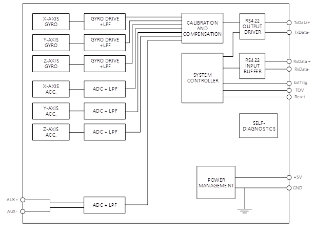
Performance Specifications and Model Selection:
The performance of the gyroscope for the general-purpose product is detailed in the table below.
Table 1:Gyroscope Specifications Table
| Parameter(gyros) | Conditions | Min | Nom | Max | Unit | Note |
| Full Scale | 500 | deg/s | 1 | |||
| Resolution | 24 | bits | ||||
| Scale Factor | 25℃ | 15000 | Isb/deg/s | Nominal Value | ||
| Scale Factor Repeatability(1σ) | <30 | ppm | 2 | |||
| Scale Factor Nonlinearity(1σ) | <150 | ppm | 3 | |||
| Bandwidth(-3dB) | 16 | 262 | Hz | Configurable | ||
| Sample Rate | 2000 | samples/s | Configurable | |||
| Bias Instability (Allan) | Allan Variance @25°C | <0.3 | deg/h | |||
| Bias Stability@10s | <3 | deg/h | ||||
| Bias Stability @1s | <7.5 | deg/h | ||||
| Bias Temperature Drift(1σ) | <20 | deg/h | Over the full temperature range | |||
| Bias Repeatability(1σ) | <3 | deg/h | ||||
| Broadband Noise | 25℃ | <0.4 | deg/s | |||
| G-Value Sensitivity | <1 | °/hr/g | Three-axis direction | |||
| Vibration Rectification Error(VRE) | (12gRMS,20-2000HZ) | <1 | °/hr/g | |||
| Power-Up Time | 750 | ms |
Note 1: The gyroscope maintains a saturated output state at ±105% FS when exceeding the measurement range.
Note 2: Performance metrics are repeated daily from the specified operating temperature.
Table 2:Accelerometer Specifications Table
| Parameter(accelerometers) | Conditions | Min | Nom | Max | Unit | Note |
| Full Scale | ±10 | g | 4 | |||
| Resolution | 24 | bits | ||||
| Scale Factor Accuracy | Calibration Accuracy | 266 | 270 | 274 | mv/g | |
| Long-Term Scale Factor Stability Scale Factor Temperature Coefficient | @20℃ | 20 | 300 120 | 220 | ppm ppm/℃ | |
| Non-Linearity | IEEE Norm,% of full scale | 0.3 | 1.0 | % | ||
| Bandwidth(-3dB) | 16 | 262 | Hz | Configurable | ||
| Sample Rate | 2000 | samples/s | Configurable | |||
| Bias switch on/off repeatability | 0.75 | mg | ||||
| Bias Stability | 0.15 | mg | ||||
| Bias Error Under Temperature Influence Long-Term Zero Bias Repeatability@20℃ | ΔT ≤ ±1°C/min @1000g @6000g | -2 | ±0.5 1.5 7.5 | 2 | mg/℃ mg mg |
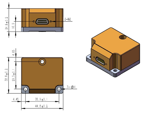
Mechanical dimensions:
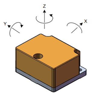
Definition of axes:
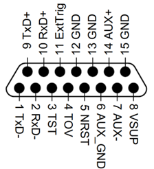
Pin configuration:
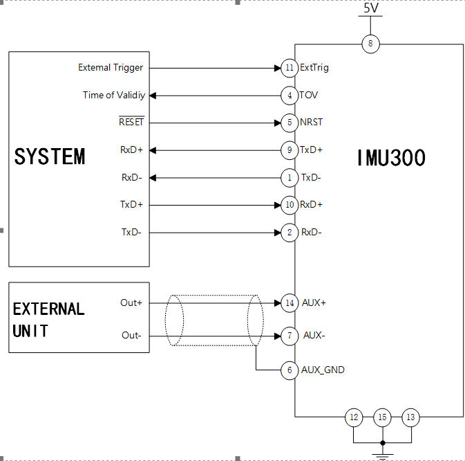
Connection Configuration:
REQUEST A QUOTE
You must be logged in to submit the form.
FAQs
Does this module include a built-in GPS receiver?
No, the HS-MX1203GT module itself does not have a built-in GPS. It requires an external active GPS/BeiDou antenna connected via its MCX-female connector to obtain its own position, which is essential for transmitting AIS messages.
What is the default configuration, and how do I program it for my vessel?
The module ships with generic factory settings. You must configure it with your vessel's specific MMSI number, name, and call sign using our provided AIS CONFIGURATION PC software and a TTL-to-USB adapter cable. Once configured, these details are stored in the module.
Can I temporarily turn off the AIS transmission (Silent Mode)?
Yes. The module features a SILENT pin. By pulling this pin low (to GND), you can disable AIS transmission for privacy or in security-sensitive areas while continuing to receive AIS data from other vessels.
What kind of antenna should I use with this module?
You need two separate VHF antennas:
A dedicated GPS/GLONASS/BeiDou active antenna for the GPS port.
Using high-quality, properly installed antennas is critical for optimal performance.
A dedicated AIS VHF antenna for the VHF port.
I'm designing a new device. Is technical documentation available?
Yes. We provide comprehensive documentation for integrators, including:
Schematic for Typical Application Circuits
Please contact our technical support team to access these resources.
Datasheet & Pinout Definitions
NMEA Protocol Guide
Configuration Command Manual
What is the Minimum Order Quantity (MOQ) for this module?
The MOQ for standard models like the HS-MX1203GT is typically 10 units. We also support customizations for larger volume orders. Contact our sales team for an exact quote.
Do you offer sample orders for testing and evaluation?
Yes, we encourage and support product evaluation. Sample orders are available. Please get in touch with us to arrange a sample and discuss your testing requirements.
Still have questions? Contact our technical sales team for expert advice.