Haisi Measurement and Control Technology


Micro-Mechanical Inertial Measurement Unit IMU313C – High-Precision MEMS IMU | 22.4×22.4mm, ±450°/s, ±10g

PRODUCT PARAMETERS
Description
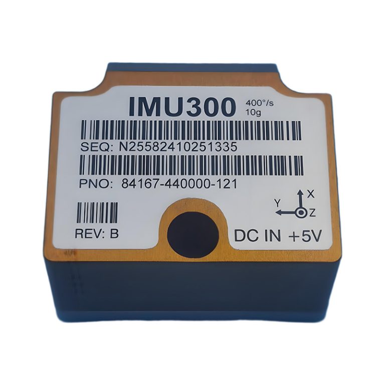
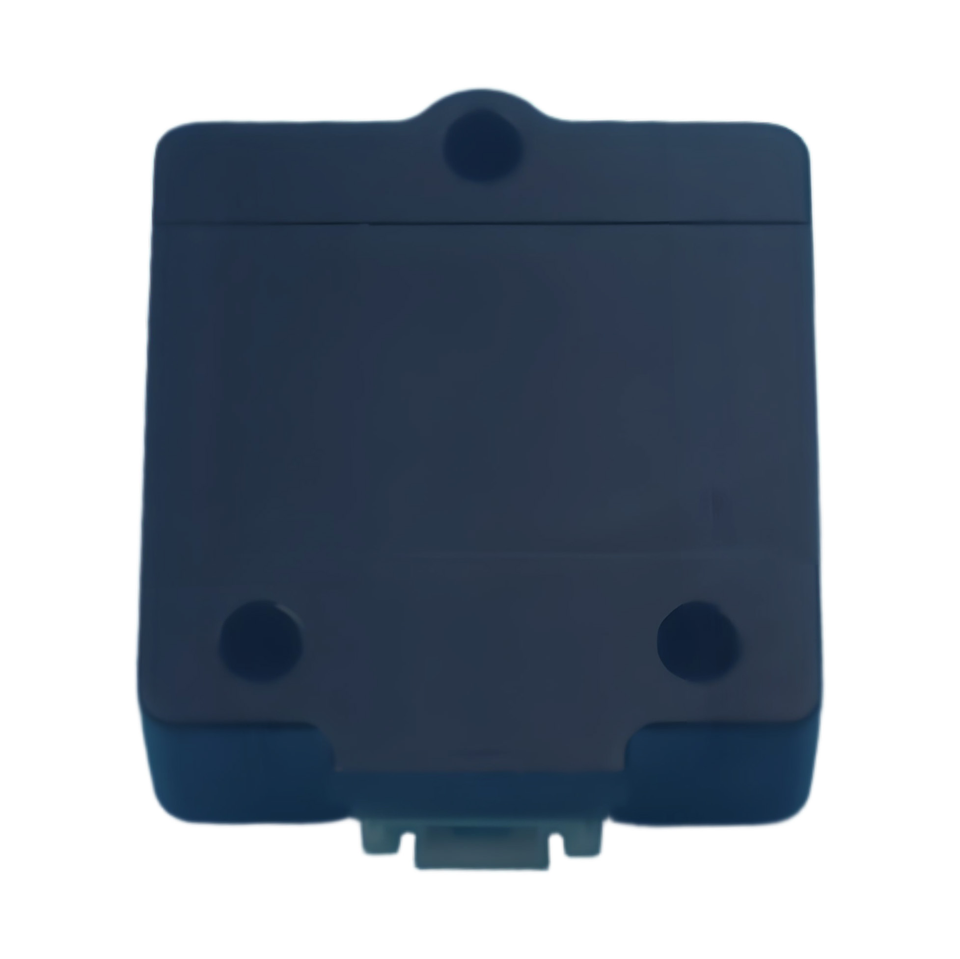
MEMS IMU
The IMU313C is an ultra-compact, high-performance 6-axis MEMS Inertial Measurement Unit (IMU). With a miniature footprint of just 22.4×22.4x9mm and a weight under 20g, it delivers precise three-axis angular rate and acceleration data, making it the ideal motion-sensing solution for size and weight-constrained applications.
Key Features & Benefits
- Ultra-Compact & Lightweight: Minimal size (22.4×22.4x9mm) and weight (<20g) for easy integration.
High Precision Sensing: Features a ±450°/s gyroscope and a ±10g accelerometer with excellent bias stability. - High-Speed Data Interface: UART TTL interface with a high 921600 baud rate and configurable data output up to 400Hz.
- Robust Performance: Operates reliably across a wide temperature range (-40°C to +85°C) and under high vibration (≥20grms).
- Simple Integration: Standard Molex connector and straightforward communication protocol simplify design-in.
Target Applications
- This miniature MEMS IMU is perfectly suited for:
- Unmanned Aerial Vehicles (UAVs) and Drones
- Robotics and Automated Guided Vehicles (AGVs)
- Platform Stabilization and Control Systems
- Industrial Navigation and Motion Tracking
- Any application requiring high-precision motion sensing in a tiny package.
Main Performance
| performance parameter | ||
|---|---|---|
| Top | Measuring Range | |
| Full Temperature Zero Bias | ≤150°/h | |
| Angular Random Walk | ≤0.25°/ | |
| Zero Bias Instability(Allan) | ≤2.5°/h | |
| Full Temperature Zero Bias Stability(1σ) | ≤10°/h | |
| Full Temperature Zero Bias Repeatability(1σ) | ≤10°/h | |
| Scale Factor Nonlinearity | ≤50ppm | |
| Bandwidth (Adjustable from 10 Hz to 250 Hz) | 150Hz | |
| Accelerometer | Measuring Range | |
| Full Temperature Zero Bias | ≤5mg | |
| Rate Random Walk | ≤0.025m/s/ | |
| Zero Bias Instability(Allan) | ≤0.025mg | |
| Full Temperature Zero Bias Stability(1σ) | ≤0.2mg | |
| Full Temperature Zero Bias Repeatability(1σ) | ≤0.2mg | |
| Scale Factor Nonlinearity(±1g) | ≤200ppm | |
| Bandwidth (Adjustable from 10 Hz to 250 Hz) | 150Hz | |
| Supply Electricity | 5V±0.3V | |
| Working Temperature | -40℃~+85℃ | |
| Resist The Impact | ≥2000g | |
| Vibrate | ≥20grms | |
| Outline Dimension | 22.4mm×22.4mm×9mm | |
| Weight | ≤20g | |
| Data Update Rate (Adjustable) | 400Hz | |
| Interface Type | UART TTL | |
| Connector | Molex 5015680607 | |
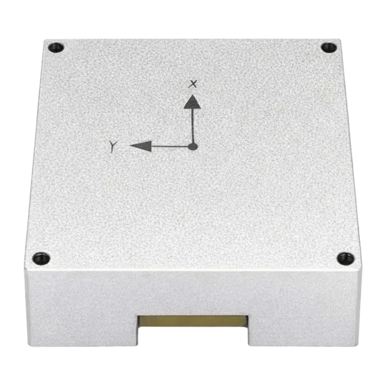
Overall dimensions and mechanical interface
Product dimensions: (22.4±0.2) mm×(22.4±0.2) mm×(9.0±0.2) mm;
Mechanical interface: 3 2.5 mm screw holes;
As shown in figure 2.
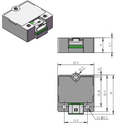
Product outline dimension drawing (unit: mm)
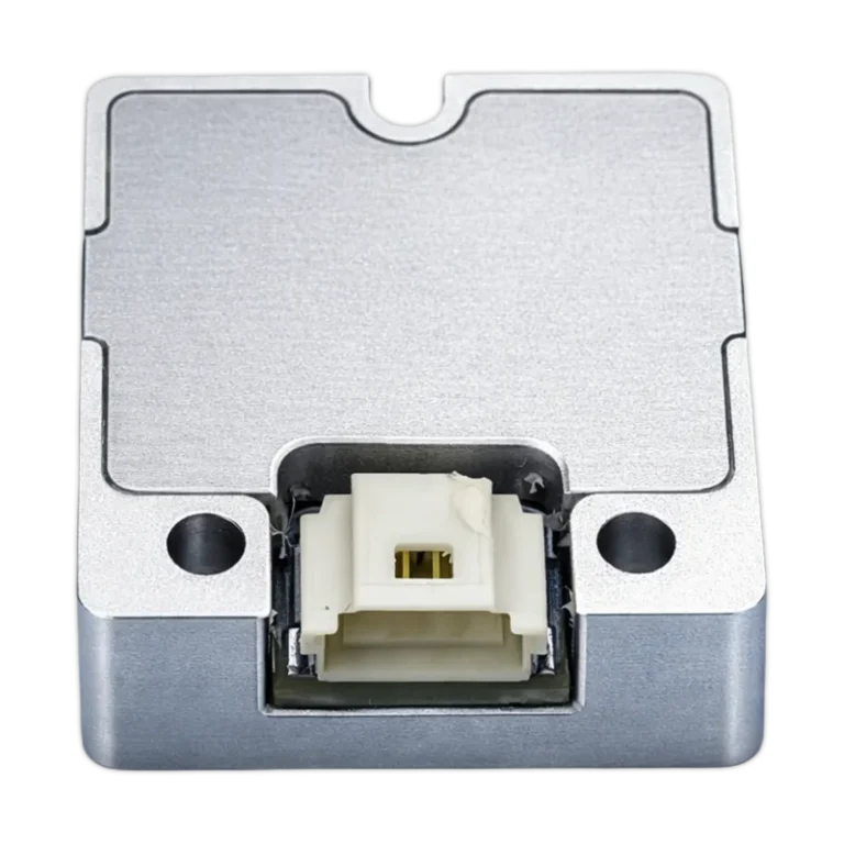
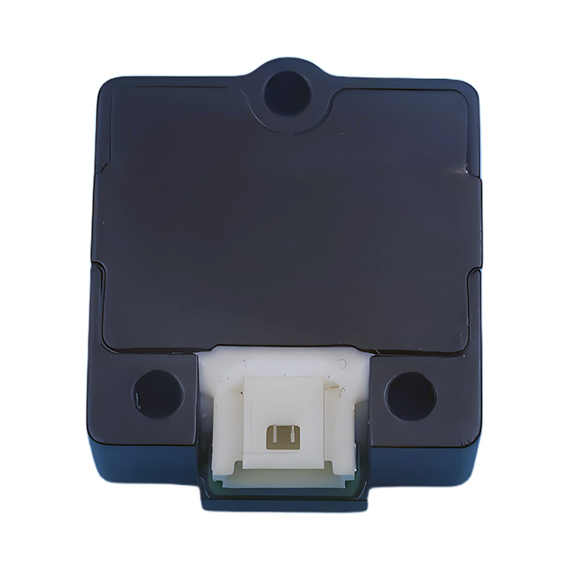
Electrical Interface
The product interface is a Molex connector.
The product connector model: 5015680607, and its definition is shown in Figure 3 and Table 2.
Counter plug connector model: 5013300600
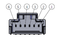
Figure 2 Product Output Interface Pin Definition Diagram
| Dit | Definition | Remarks |
| 1 | VCC(+5V) | Power supply positive |
| 2 | GND | Power supply ground |
| 3 | TXD | TTL transmission |
| 4 | RXD | TTL reception |
| 5 | PPS | Synchronize |
| 6 | — | — |
Communication Protocol
TTL level communication is adopted, with a baud rate of 921600bps, 1 start bit, 8 data bits, 1 stop bit, no check, low byte in front, and high byte in the back. The refresh rate is 400Hz, and the communication protocol is shown in Table 3.
| Byte | Value | Value Type | Describe |
| 0 | 0xBD | / | Fixed |
| 1 | 0xDB | ||
| 2 | 0x0A | ||
| 3~6 | LSB MID1 MID2 MSB | Float | Gx Factor 1 Unit deg/s |
| 7~10 | LSB MID1 MID2 MSB | Float | Gy Factor 1 Unit deg/s |
| 11~14 | LSB MID1 MID2 MSB | Float | Gz Factor 1 Unit deg/s |
| 15~18 | LSB MID1 MID2 MSB | Float | Ax Factor 1 Unit m/s2 |
| 19~22 | LSB MID1 MID2 MSB | Float | Ay Factor 1 Unit m/s2 |
| 23~26 | LSB MID1 MID2 MSB | Float | Az Factor 1 Unit m/s2 |
| 27 | LSB | Signed | Counter Factor 1 Minimum 0 Maximum 65535 Unit ms |
| 28 | MSB | ||
| 29 | BIT | UnSigned | Built-in Test Self-checking error (tentative 00) |
| 30 | Reserved | Reserved | Reserved (Arrange for the time being 00) |
| 31 | LSB | UnSigned | Temperature Factor 0.006 Minimum -60 Maximum +125 Unit ℃ |
| 32 | MSB | ||
| 33 | Check | Byte | Temperature Factor 0.006 Minimum -60 Maximun +125 Unit ℃ |
2.6 Coordinate
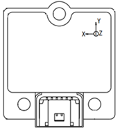
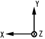
Figure 3 Product Coordinate System
For more information, please check the data sheet in PDF
Product installation
When installing the product, install it in the designated installation position with 3 M2 or M2.5 screws. The installation requirements for products are as follows:
1) Install with M2 or M2.5 screws. See Figure 2 for the installation dimensions.
2) Clean the installation space to facilitate product installation.
3) Clean the adhered impurities on the product and the installation surface.
4) Place the product carefully to avoid bumping.
5) After the product is placed, there should be no “leg sticking” phenomenon; otherwise, check whether the installation plane meets the requirements.
6) Tighten the screws in turn.
Electrical Connection
During the use of the product, it should be noted that the positive and negative connection of the power cord and each signal wire should not be wrong. It is forbidden to plug and plug the power cord and signal wire with electricity during the power-on process of the product. It is strictly forbidden to disassemble the product without authorization. If the product is abnormal during use, you should contact the manufacturing unit or return to the factory for maintenance.
REQUEST A QUOTE
FAQs
Does this module include a built-in GPS receiver?
No, the HS-MX1203GT module itself does not have a built-in GPS. It requires an external active GPS/BeiDou antenna connected via its MCX-female connector to obtain its own position, which is essential for transmitting AIS messages.
What is the default configuration, and how do I program it for my vessel?
The module ships with generic factory settings. You must configure it with your vessel's specific MMSI number, name, and call sign using our provided AIS CONFIGURATION PC software and a TTL-to-USB adapter cable. Once configured, these details are stored in the module.
Can I temporarily turn off the AIS transmission (Silent Mode)?
Yes. The module features a SILENT pin. By pulling this pin low (to GND), you can disable AIS transmission for privacy or in security-sensitive areas while continuing to receive AIS data from other vessels.
What kind of antenna should I use with this module?
You need two separate VHF antennas:
A dedicated GPS/GLONASS/BeiDou active antenna for the GPS port.
Using high-quality, properly installed antennas is critical for optimal performance.
A dedicated AIS VHF antenna for the VHF port.
I'm designing a new device. Is technical documentation available?
Yes. We provide comprehensive documentation for integrators, including:
Schematic for Typical Application Circuits
Please contact our technical support team to access these resources.
Datasheet & Pinout Definitions
NMEA Protocol Guide
Configuration Command Manual
What is the Minimum Order Quantity (MOQ) for this module?
The MOQ for standard models like the HS-MX1203GT is typically 10 units. We also support customizations for larger volume orders. Contact our sales team for an exact quote.
Do you offer sample orders for testing and evaluation?
Yes, we encourage and support product evaluation. Sample orders are available. Please get in touch with us to arrange a sample and discuss your testing requirements.
Still have questions? Contact our technical sales team for expert advice.