Haisi Measurement and Control Technology


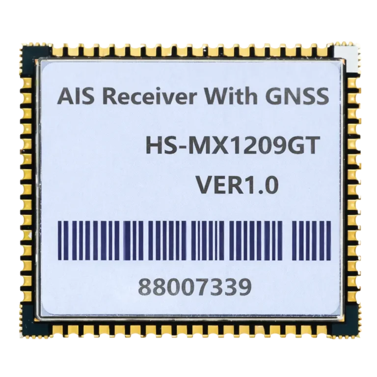
HS-MX1203GT: High Performance Embedded Class B & B+ AIS Transceiver Module
PRODUCT PARAMETERS
Description
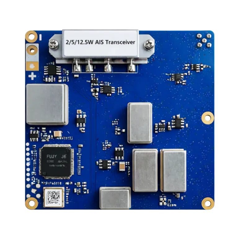
The HS-MX1203GT is a next-generation, compact embedded AIS transceiver module supporting both Class B (2W CSTDMA) and Class B+ (5W SOTDMA) operations. With ultra-compact 70x70x14mm dimensions and comprehensive interface support, it provides the perfect embedded solution for vessel navigation systems, unmanned vehicles, and maritime IoT applications.
Features and Specifications
- Utilizes a dedicated low-power processor chip supporting full Class B AIS protocol
- Integrates full-stack baseband processing and RF transceiver functionality
- Meets ultra-high sensitivity reception requirements down to -119dBm
- Supports software upgrades and device control via TTL serial port
- Support automatic reception and processing of AIS information from other vessels or VTS shore stations
- Supports multiple data format interfaces, including NMEA2000, NMEA0183, and GNSS
- Can extract position, heading, speed, and other information, encapsulating it according to the standard format of AIS messages
- Capable of connecting to and transmitting data to shipboard multifunction displays and other naval equipment, enabling ship-to-ship and ship-to-shore interconnection and collaboration
- Complies with IEC 60945, IEC 62287-1/2, IEC61162-1/2, IEC61108-1, ITU-R M1371-5 and NMEA2000 @ Edition2.20 standards
- Ultra-compact dimensions: 70mm x 70mm x 14mm
- Suitable for general marine navigation and communication systems, shore-based portable base stations, inland waterway and offshore navigation buoys, offshore platforms, marine buoys, offshore wind farm electronic fences, inland electric vessels, unmanned vessels, and bridge collision avoidance warning systems.
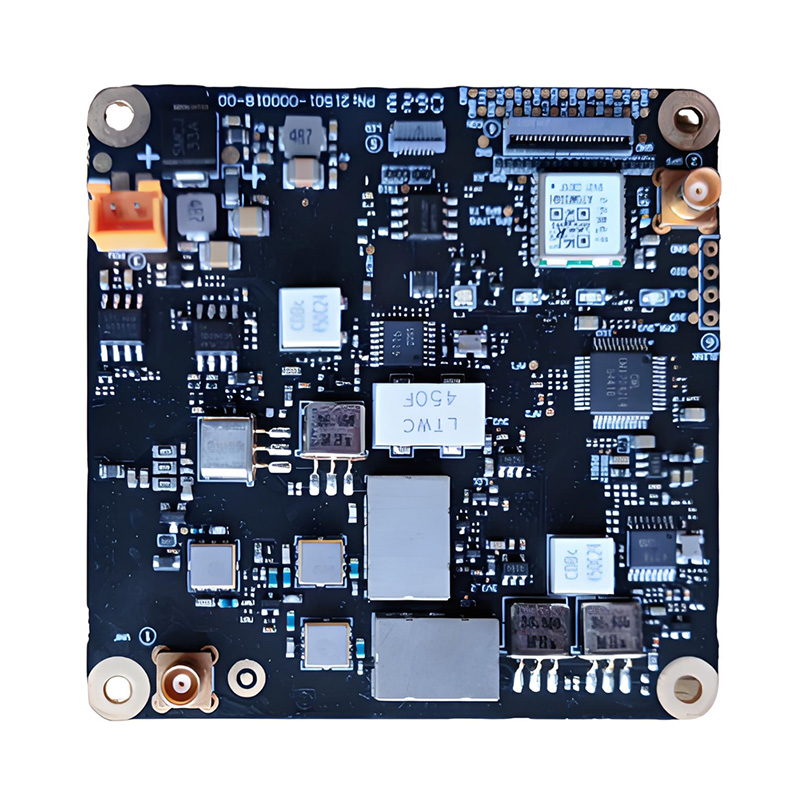
Dimensions
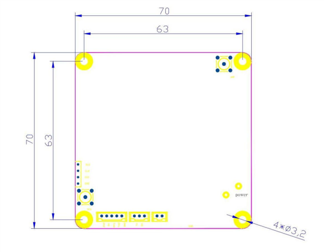
Figure 2 Module size diagram (70 mm x 70mm x 14mm)
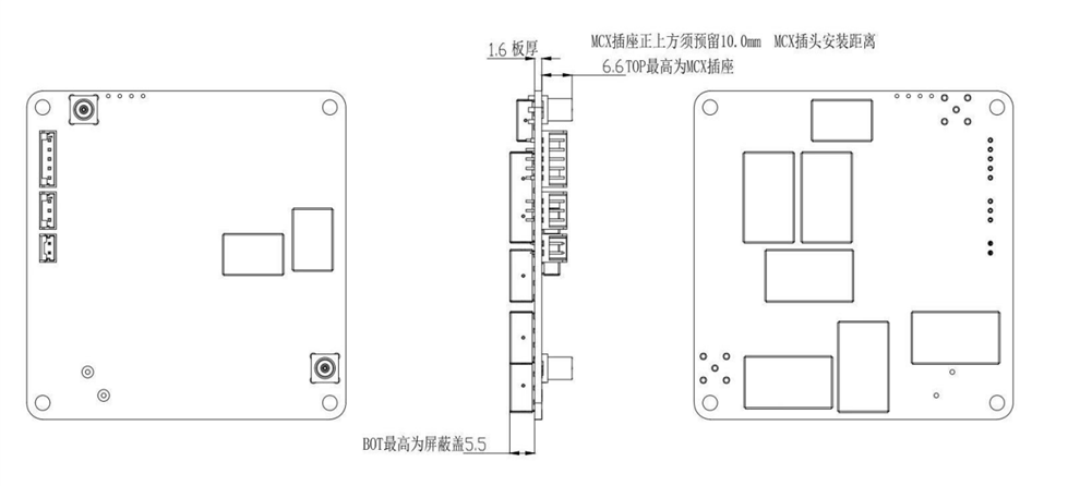
Figure 3 HS-MX1203GT 3D Height Limit Diagram
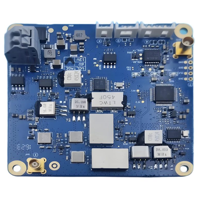
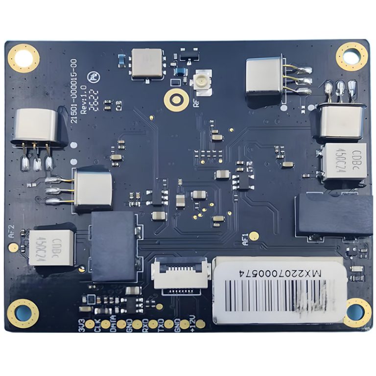
Interface Definitions
| Connector ① | |||
| Serial Number | Definition | Connection Instructions | Remarks |
| ① | VHF | Connect to the AIS Antenna | MCX(Female) |
| Connector ② | |||
| Serial Number | Definition | Connection Instructions | Remarks |
| ② | GPS | Connect to the GPS/BeiDou Antenna | MCX(Female) |
| Connector ③ | |||
| Serial Number | Definition | Connection Instructions | Remarks |
| ③ | – | Power Supply, Negative | |
| + | Power Supply, Positive,_12V DC | ||
| Connector ④ | |||
| Serial Number | Definition | Connection Instructions | Remarks |
| 1 | GND | Ground | |
| 2 | TX1 | TTL1 Serial Port Signal Output | |
| 3 | RX1 | TTL1 Serial Port Signal Input | |
| 4 | GND | Ground | |
| 5 | TX2 | TTL2 Serial Port Signal Output | |
| 6 | RX2 | TTL2 Serial Port Signal Input | |
| 7 | GND | Ground | |
| 8 | NC | Floating | |
| 9 | NC | Floating | |
| 10 | GND | Ground | |
| 11 | CTX | CAN Signal Output | |
| 12 | CRX | CAN Signal Input | |
| 13 | GND | Ground | |
| 14 | TX3 | External GPS Signal Output | |
| 15 | RX3 | External GPS Signal Input | |
| 16 | PPS | External GPS UTC Input | |
| 17 | GND | Ground | |
| 18 | SLT | SILENT MODE (Active Low) | |
| 19 | NC | Floating | |
| 20 | NC | Floating | |
| 21 | NC | Floating | |
| 22 | NC | Floating | |
| 23 | WKP | Floating | |
| 24 | GND | Ground | |
| Connector ⑤ (LED indicator) | |||
| Serial Number | Definition | Connection Instructions | Remarks |
| 1 | GND | Ground | |
| 2 | LED ERRO | Device Error Indicator | |
| 3 | LED GPS | GPS Status Indicator | |
| 4 | LED RX | Device Rx Status Indicator | |
| 5 | LED TX | Device Tx Status Indicator | |
| 6 | LED OTHER | Device Other Status Indicator | |
| 7 | 3V3 IN | 3.3V Voltage Input | |
| 8 | GND | Ground | |
| 9 | GND | Ground | |
| 10 | GND | Ground | |
Table 2 Interface Definitions
Connections
Power Supply
The module’s power supply is connected to pin ③ on the board via a 12VDC regulated power supply. Ensure correct polarity is maintained
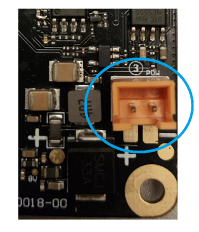
Figure 4 Power Interface
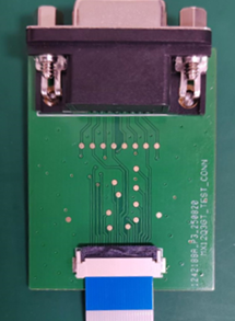
Data and Communication Interface
The module’s external data communication and control ports must be connected to the 24-pin composite communication interface on pin ④ of the board. Refer to Table 1 for pin definitions.
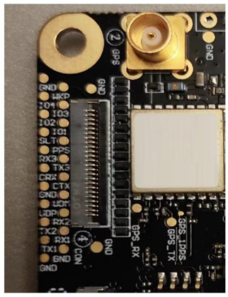
Figure 5 Composite Data Communication Interface
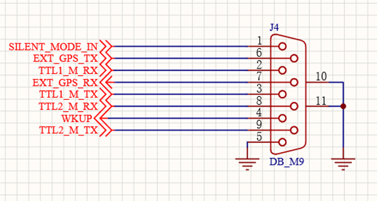
| Pin | Function | Description | Remarks |
| 1 | SILENT_MODE_IN | Silent Mode Input | Active low |
| 2 | TTL1_M_RX | Serial Port 1 Data Input | 3.3V TTL |
| 3 | TTL1_M_TX | Serial Port 1 Data Output | 3.3V TTL |
| 4 | WKUP | WKUP function | Software not supported |
| 5 | GND | Ground | |
| 6 | EXT_GPS_TX | External GPS Data Output | When using external GPS |
| 7 | EXT_GPS_RX | External GPS data input | When using external GPS |
| 8 | TTL2_M_RX | Serial Port2 Data Input | This port is currently disabled |
| 9 | TTL2_M_TX | Serial Port2 Data Output | This port is currently disabled |
Figure 6 External Communication Serial Port Adapter Board and Definitions
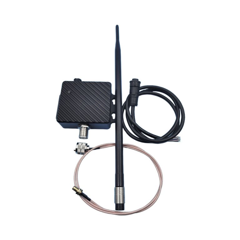
AIS and GPS Antenna Connections
The external AIS antenna connects via the board’s VHF port ①, while the GPS antenna connects via the board’s GPS port ②. Never power on the module without both AIS and GPS antennas connected
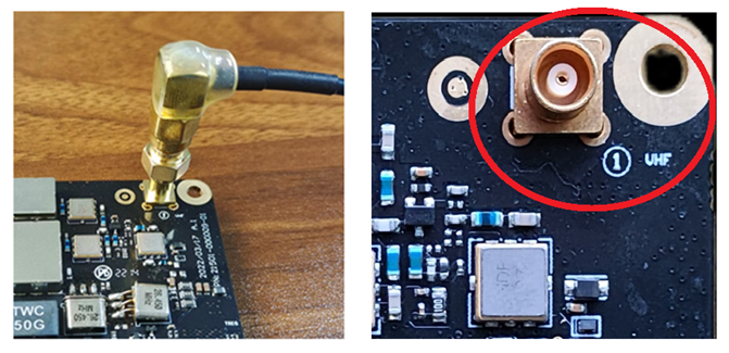
Figure 7 VHF Antenna Connection
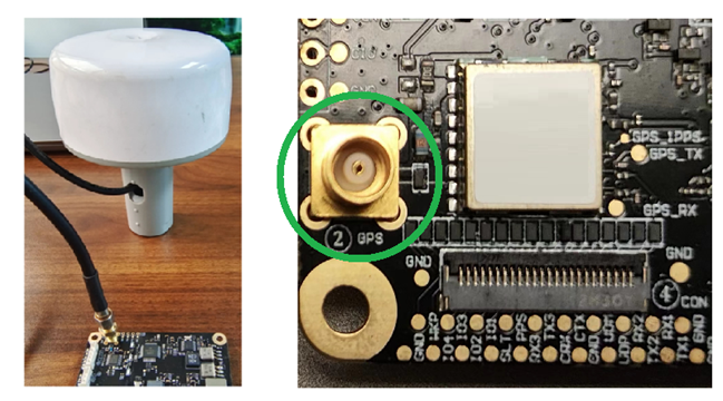
Figure 8 GPS Antenna Connection
LED Status Indicators
Operating and status indicators are defined in Table 2 under Interface ⑤.
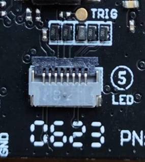
Figure 9 Operating and Status Indicator Interface
Application Notes
- The HS-MX1203GT accepts 12V or 24V DC power input. After power-up, allow 1 second for initialization before normal operation begins.
- The UART1 is a standard 3.3V TTL serial port data output with a baud rate of 38400bps.
- The UART2 is reserved for the serial port and has no data output.
- Module Configuration MMSI needs to be configured, and the output is the source data of the AIS message, which needs to be when the vessel has a power cut-off controller, HS-MX1203GT power
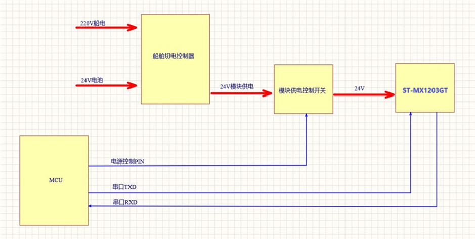
Figure 10 HS-MX1203GT Power Control Recommendation
Software Configurations
Power Settings
The default power setting of the module factory is 2W. The high, medium and low power setting commands are as follows:
1)5W,$PAIS,CMD,7,CFG,TX_POWER,H,040 2)2W,$PAIS,CMD,7,CFG,TX_POWER,M,045
3)1W,$PAIS,CMD,7,CFG,TX_POWER,L,0*44
Other configurations
Please refer to the HS-MX1203GT Configuration Command Guide.
REQUEST A QUOTE
FAQs
Does this module include a built-in GPS receiver?
No, the HS-MX1203GT module itself does not have a built-in GPS. It requires an external active GPS/BeiDou antenna connected via its MCX-female connector to obtain its own position, which is essential for transmitting AIS messages.
What is the default configuration, and how do I program it for my vessel?
The module ships with generic factory settings. You must configure it with your vessel's specific MMSI number, name, and call sign using our provided AIS CONFIGURATION PC software and a TTL-to-USB adapter cable. Once configured, these details are stored in the module.
Can I temporarily turn off the AIS transmission (Silent Mode)?
Yes. The module features a SILENT pin. By pulling this pin low (to GND), you can disable AIS transmission for privacy or in security-sensitive areas while continuing to receive AIS data from other vessels.
What kind of antenna should I use with this module?
You need two separate VHF antennas:
A dedicated GPS/GLONASS/BeiDou active antenna for the GPS port.
Using high-quality, properly installed antennas is critical for optimal performance.
A dedicated AIS VHF antenna for the VHF port.
I'm designing a new device. Is technical documentation available?
Yes. We provide comprehensive documentation for integrators, including:
Schematic for Typical Application Circuits
Please contact our technical support team to access these resources.
Datasheet & Pinout Definitions
NMEA Protocol Guide
Configuration Command Manual
What is the Minimum Order Quantity (MOQ) for this module?
The MOQ for standard models like the HS-MX1203GT is typically 10 units. We also support customizations for larger volume orders. Contact our sales team for an exact quote.
Do you offer sample orders for testing and evaluation?
Yes, we encourage and support product evaluation. Sample orders are available. Please get in touch with us to arrange a sample and discuss your testing requirements.
Still have questions? Contact our technical sales team for expert advice.